Reaction Path Following
Once a transition state has been located and its characteristics have been verified, the (usually) two minima connected by the transition state have to be localized. This is done by calculating the intrinsic reaction coordinate (IRC) from the transition state in the forward and reverse direction. IRC calculations are performed in MOPAC using the IRC keyword in combination with other keywords specifying further details of the calculation. The IRC algorithm in MOPAC differs from that for the calculation of the dynamic reaction coordinate (DRC) in that the kinetic energy of the system is quenched at each step, thus lowering the potential as well as the total energy of the system along the pathway. In DRC calculations the total energy of the system (= kinetic + potential) is conserved throughout the calculation.
The direction of the IRC calculation (forward or reverse) is indicated through modification of the IRC keyword itself. Specification of IRC=1 indicates a forward IRC calculation along the normal coordinate 1 (as given in the output of a FORCE calculation). Calculation of the reverse path is indicated with IRC=-1.
The question of selecting points on the IRC path is determined by the keyword X-PRIORITY=n.nn. The values of n.nn are given in Angstroms and define the distance between two points on the IRC path. It is also possible to select the points according to an energetic criterion with H-PRIORITY=n.nn. In this latter case, the parameters supplied to MOPAC are in kcal/mol (default: 0.10 kcal/mol).
The keyword LARGE controls output of structural and energetic data along the IRC path. The most important version of this keyword is LARGE=n printing the internal coordinates for each nth point along the path. Usually it is sufficient to print the structures of only every 5th or 10th point to the output file.
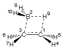
The following sample input file calculates the forward IRC for the reaction of BH3 with ethylene. The IRC points are selected according to the distance criterion 5pm apart. The structure of each of the points is printed to the output file.
AM1 T=128H IRC=1 X-PRIORITY=0.05 LARGE=1
forward irc for TS ethylene + BH3 (AM1)

  C     .0000000  0       .000000  0       .000000  0    0    0    0
  B    2.0254361  1       .000000  0       .000000  0    1    0    0
  C    1.8489696  1     41.028697  1       .000000  0    2    1    0
  H    1.1006641  1    122.125964  1     93.675234  1    1    3    2
  H    1.1006729  1    122.109035  1    -93.225358  1    1    3    2
  H    1.1027191  1    121.763107  1     99.808821  1    3    1    2
  H    1.1027246  1    121.733627  1   -100.158220  1    3    1    2
  H    1.1967850  1    111.512331  1    -71.329279  1    2    1    3
  H    1.2074279  1     76.230329  1    179.061288  1    2    1    3
  H    1.1969267  1    112.238165  1     69.677640  1    2    1    3
|
 |
As a first step MOPAC calculates the force constant matrix and the normal modes of the system. According to the X-PIORITY criterion, selected structures are then dumped to the output file. One sample entry (entry 124) close to the end of the IRC path holds the following information:
     POINT   POTENTIAL  +  ENERGY LOST   =   TOTAL      ERROR    REF%   MOVEMENT
     697       4.29242     44.77625         49.06867    .01651   124   %  4.3716


          FINAL GEOMETRY OBTAINED                                 CHARGE
 AM1 T=128H IRC=1 X-PRIORITY=0.05 LARGE=1
 forward irc for TS ethylene + BH3 (AM1)

   C     .000000  0     .000000  0     .000000  0   0  0  0       -.1888  124AA*
   B    2.395315  1     .000000  0     .000000  0   1  0  0        .2713  124AB*
   C    1.512288  1   38.872202  1     .000000  0   1  2  0       -.3180  124AC*
   H    1.115370  1  124.868197  1  279.453446  1   1  2  3        .0774  124AD*
   H    1.115375  1  124.364396  1   81.205154  1   1  2  3        .0774  124AE*
   H    1.112609  1  112.056316  1  118.687009  1   3  1  2        .0891  124AF*
   H    1.112616  1  112.066102  1  241.288177  1   3  1  2        .0891  124AG*
   H    1.190958  1  111.593578  1  248.955072  1   2  1  3       -.0806  124AH*
   H    2.299193  1   27.558730  1  179.614054  1   2  1  3        .0637  124AI*
   H    1.190961  1  111.742070  1  110.919849  1   2  1  3       -.0805  124AJ*
What is listed as "POTENTIAL ENERGY" is the heat of formation of the current structure (subsequently printed in internal coordinates). The "ENERGY LOST" is the cumulative kinetic energy quenched out of the system since initiation of the IRC calculation. The sum of these two energies should always be constant and equal to the heat of formation of the starting point of the IRC path (usually the transition state). The variation in "TOTAL" energy along the IRC path listed as "ERROR" can be taken as a measure of the numerical accuracy of the IRC path calculation. The structures dumped to the output file are referenced through the number given as "REF%". The overall movement relative to the transition state is numerically described by the "MOVEMENT" variable.
The initial momentum supplied to normal mode 1 in this case is exactly one quantum of vibrational energy. In cases, in which a larger inital momentum is desirable, this can be adjusted with the KINETIC=n keyword. Using, for example, IRC=1 KINETIC=1, an initial momentum of 1 kcal/mol is supplied to normal mode 1. This option is particularly helpful on flat potential energy surfaces.
The use of symbols such as "%" and "AB*" in these entries allows for an easy extraction of data for all structures along the path using the grep command (grepping for "%", " %", "AB" etc.).
All structures contained in the IRC output file can be animated with MOLDEN by just reading in the file. The heats of formation for all structures are also collected in the Geom. conv. window.